
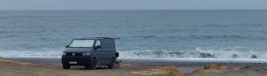
The van (aka La Furgo) has already 2 years with us. Since then, we did around 30k kms and the inside evolved quite a lot. Zooming in into the electrics, La Furgo came with a second (lead) battery and a splitter, that was feeding a heater and that's it. As we could see, it took a night for the heater to leave the battery quite empty and the splitter needed quite a lot of kms to fill it back enough for a next night.
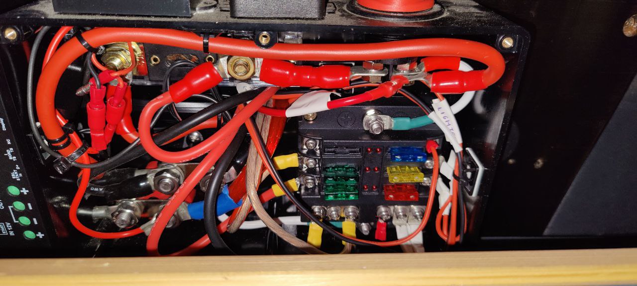
That triggered a set of actions that started with a new Booster to charge the battery faster (a Votronic VCC 1212-30) and continued with adding consumers to the battery (fridge, lights, USB chargers, more lights, even a water pumper, ...). Not only that, it also received 2 more sources of power: a mains charger and a solar panel with its own MPPT. Even the battery iterated to a Lithium one. The initial small electrical box ended up patched over patch, with lots of cables floating around and literally no space to patch more. Every time that anything had an issue, the actual problem was mine to follow the cables and to avoid destroying any other connection while performing any action.

A change was needed, and after this year's tripping season I started the project of a new electrical box.
Requirements
As per the experience, some of the requirements were quite clear
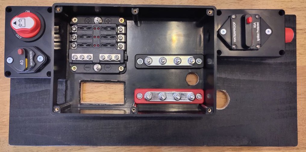
- Switches for the battery and solar panel. Thermal 40A switch for the power coming from the alternator. Thermal 50A switch to replace the 50A fuse. I want to be able to cut the power on the go and to avoid consuming so many fuses.
- The Booster needs to move somewhere more accessible. The Votronic tends to burn the internal 40A fuse (yeah, I guess the alternator is not that stable anymore) and changing the fuse on-the-go is pain. The Votronic burning fuses is also a topic for a dedicated post 😡
- There must be a busbar per pole. Over the time I have too many consumers over a single connector screw, and starts to be quite impossible to screw anything else.
- Only the required cables must be accessible. OMG the mess of seen cables is simply dangerous. And should be way easier to interchange the battery.
- The entry point of the cables has to be through the box. Currently they jump the side of the seat and enter from behind, so the point 4 above is even funnier.
Execution
So the process started with the typical sketching, enumerating the current connections in and out, correcting the sketch and placing a big buying list. I intended to do kind of a swapping so I also cut and paint a new wooden base, this time thinking about the real space and the accessibility (it was pain to come with a screw driver to add/change anything). It all went quite fast-ish, the first session brought a nice base to present the basic pieces and plan better their position.
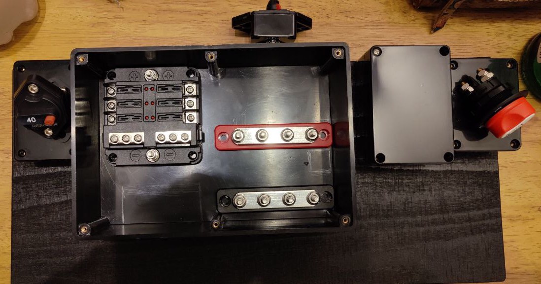
Then it's time to cut the plastic box and the wood to allocate the holes where the cables need to go through. This time I plan a big window to the inner and a separated one for the main Positive and Negative. to be honest, the main dilemma was to decide where to position the busbars. Need to be straight forward entering the box, no big curves. Decided? then screw them!
Now just attach everything I can do at home: Shunt, initial cables, ...
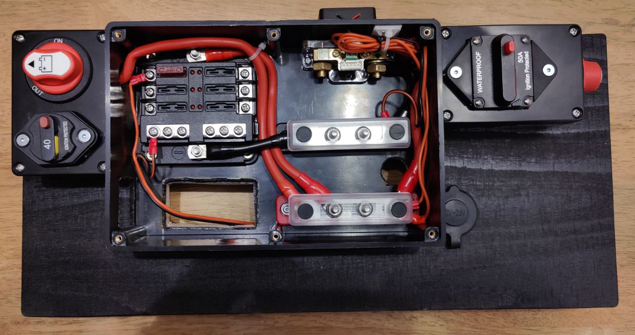
And almost ready with main Positive and Negative cables and connectors. This made the main thermal and switches already finished, and also some small details like the labels to identify what the switches act over what.
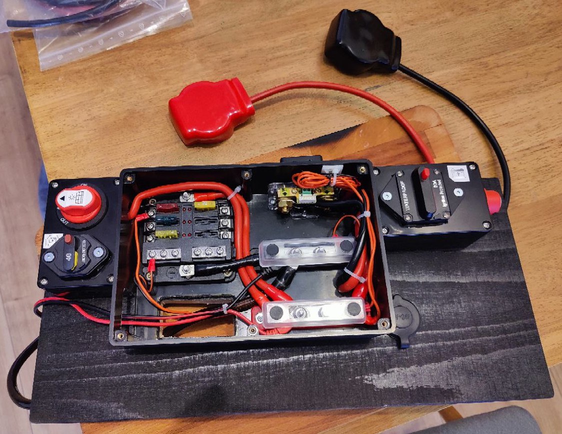
Then I spent quite a long time to install all consumers and power sources, trying to have a minimum of sense and avoid over-crowding the space. It was easily 3h in a very exhausting position. But it was worth it... and works!
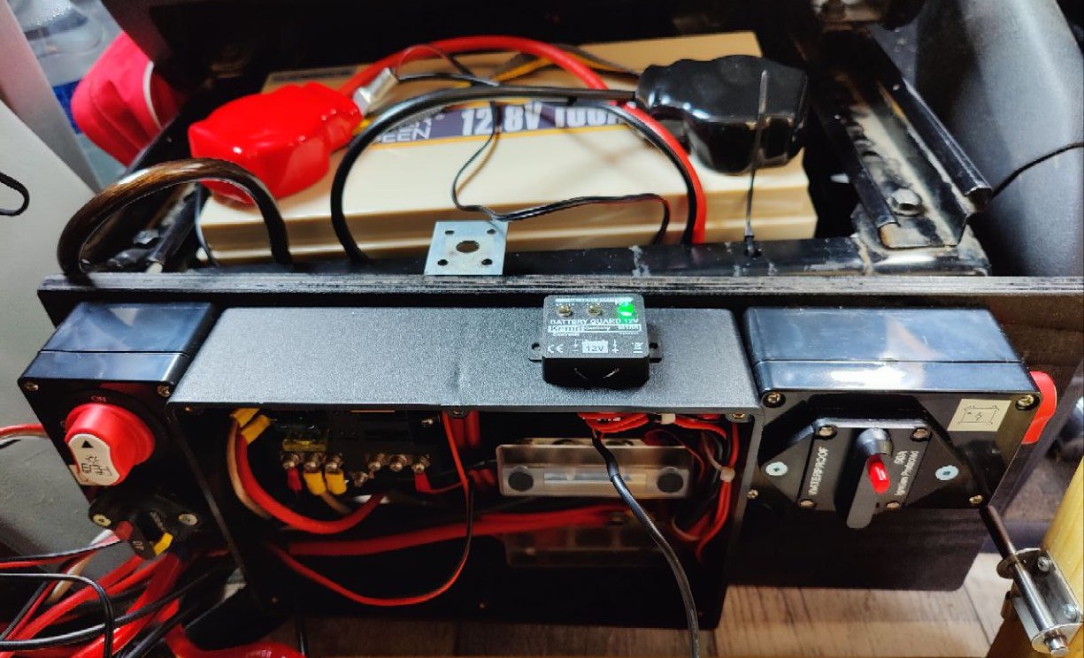
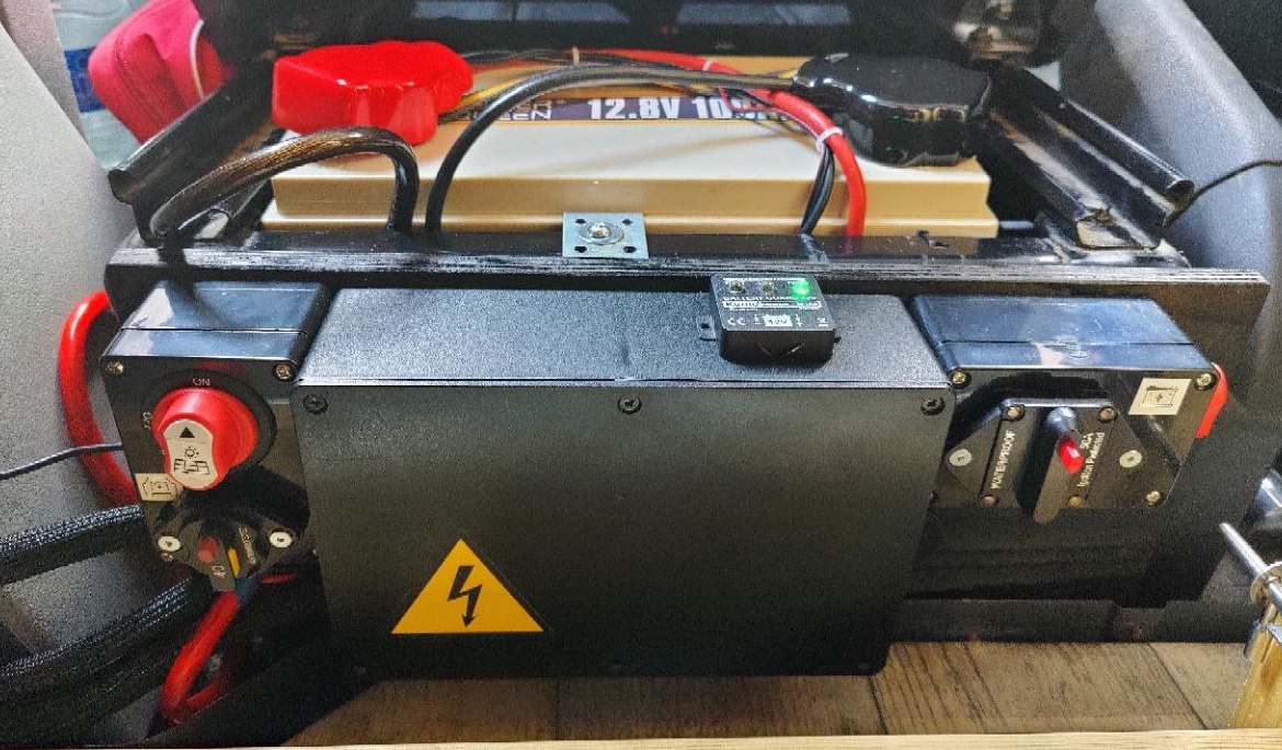
Finally, investing some more time to hide the cables and leave the setup as clean as possible. I used a cable sleeve to avoid showing the bunch of cables, and one can only see the main Positive and Negative, plus the main ground one and the two sensor cables that must go to the positive pole. to be honest, I am quite satisfied with the end result 😊

Documentation
Yes, I am a professional, and the task is not done if you don't provide documentation. So the last thing to do was to update the electric diagram of the van. And for the sake of sharing the knowledge, here it is mine:
